Building a custom keyboard
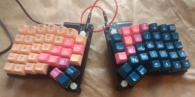
I made a custom keyboard design, the ErgoSnap.
Backstory
A while ago I built an Iris keyboard from a kit because I wanted to try a split layout. I'm pretty happy with it but after using it for a few months decided I would like a few more keys. I had a look at what else was available, and after spending a lot of time on the internet decided that the layout of the ErgoDash looked good. I liked the construction of the Mitosis using a single PCB design for both the mounting plate and the actual PCB the switches are soldered to; however I didn't want a wireless keyboard and wanted to stick with the QMK firmware. So I decided to adapt the ErgoDash design to use the Mitosis construction.
Construction
Since I was designing my own keyboard I can tailor it to my requirements:
- Tenting built in. Just need two M6 mounting holes on the inside edge of the board
- Don't care about any kind of lighting
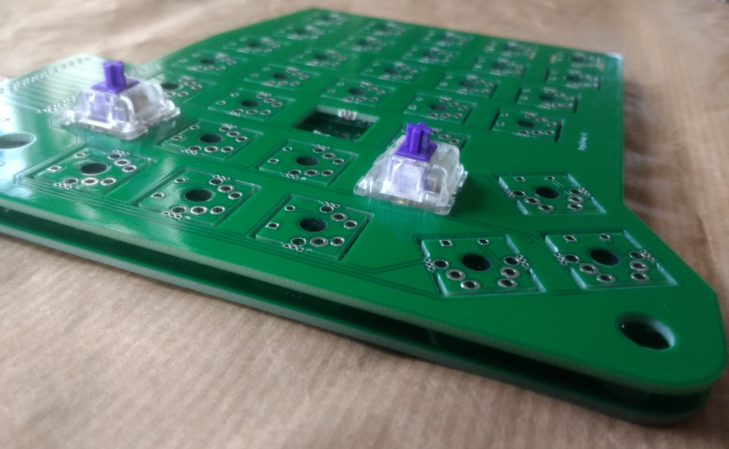
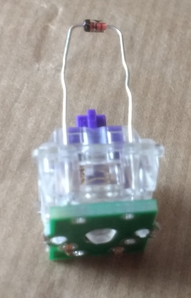
I chose to use the diode mounting holes in the keyswitches - these are wider than the LED mounting holes (but in the same location on the keyswitch). They are in the Cherry MX datasheet (found by searching around on the internet). I'm using Zealios and the ones I've got definitely have the diode holes. This simplified routing as the diode overlaps the switch.
I created a custom component and footprint with the keyswitch, diode and cutouts for snapout section (for the mounting plate PCB). Added a chin at the top for the ProMicro, used the reversible ProMicro footprint from Ergo42.
Ordered PCBs from JLC PCB:
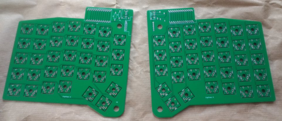
First set of PCBs arrived and looked good, but...
the holes for the diode legs were not the right distance apart! Whoops. Luckily PCBs are pretty cheap so a couple of weeks later I had revised boards. Only a few mistakes remain now. See the ErgoSnap github repo for more info.